Qimulation 3D Simulation Platform
Two modules, one data interface
The Qicheng Qimulation 3D simulation platform consists of motion simulation and 3D visualization modules. Linked through a data interface, they form an integrated system for trajectory planning, line synchronization, dynamic verification, 3D inspection and die design guidance. Simulation results feed directly back into line and die design, reducing on-site trial and error.
3D visualization is often built on general-purpose 3D design platforms, resulting in large systems, steep learning curves and high costs. Qicheng uses a fully domestic custom-built system that is autonomous, controllable, lightweight and easy to use; line engineers can get started after a short training period.
Motion simulation + 3D visualization
One proves the motion works, the other makes the space clear; together they form complete virtual validation of a stamping line.
Motion simulation
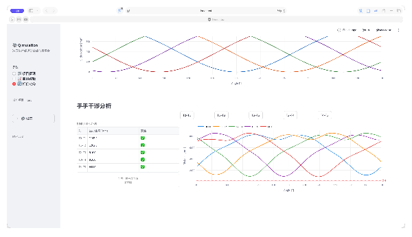
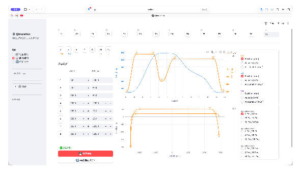
Plan trajectories for robots, manipulators and presses in a virtual environment, place all line equipment on one timeline to verify synchronization, and expose interference, overtravel and cycle-time conflicts in advance.
3D visualization
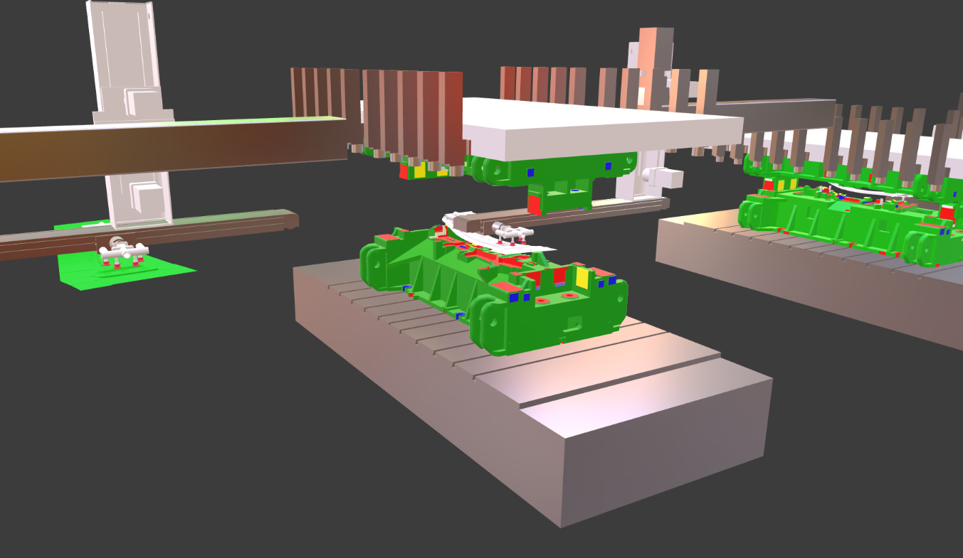
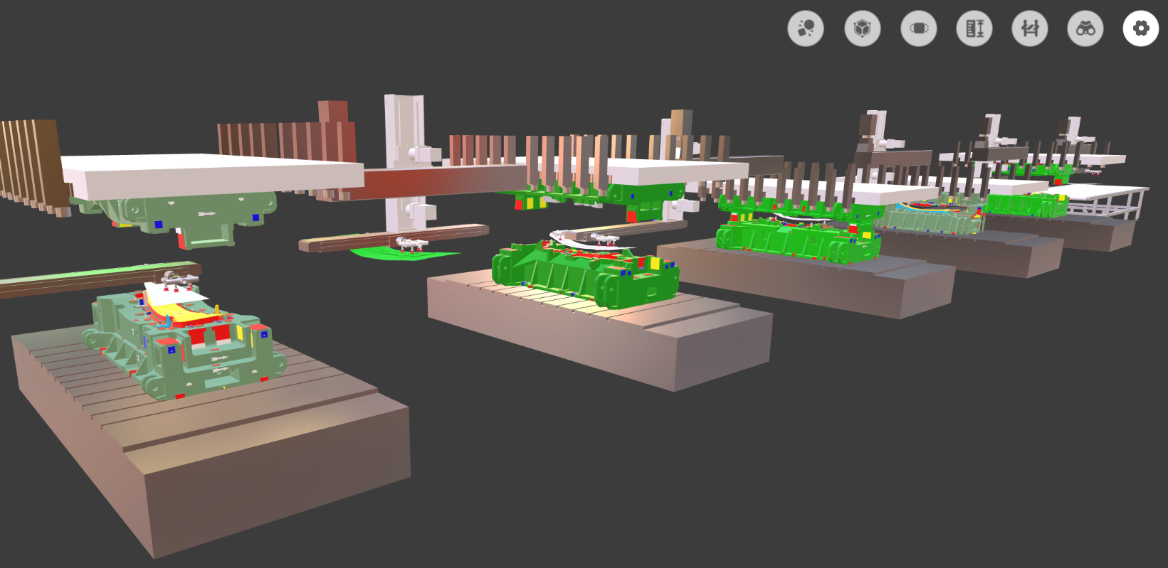
A fully domestic custom-built 3D visualization module that is lightweight, easy to use and autonomous. The full-line 3D model stays consistent with on-site equipment, dies and workpieces, supporting 3D inspection and die design guidance.
Six core capabilities in one system
From trajectory to full line, from motion to dies, simulation results flow through one data chain.
Generate motion paths from the process
Plan pick-and-place paths based on equipment parameters and workpiece geometry, reducing on-site teaching and repeated adjustments.
Unified timing across all line equipment
Presses, manipulators, conveyors and end-of-line equipment run on one timeline to verify that line cycle time meets target.
Dynamic validation happens when it moves
Dynamic demonstration of the full line reveals interference, overtravel and waiting in advance, keeping problems in the design stage.
Spatial relationships at a glance
Inspect spatial relationships among equipment, dies and workpieces in the 3D model to guide layout and structural changes.
Simulation results feed back into dies
Feed motion inspection results back into die design to shorten validation and tryout cycles for new dies.
Seamless connection between modules
Motion simulation and 3D visualization are linked through a data interface, keeping models and motion on the same version.
Compared with general-purpose 3D design software
Stamping line simulation calls for a dedicated tool, not a large general-purpose platform.
Comprehensive, but costly
- Large system with high deployment and maintenance costs
- Steep learning curve with a long ramp-up for engineers
- Designed for general scenarios, requiring custom development for stamping processes
Dedicated, lightweight and autonomous
- Fully domestic custom development, autonomous and controllable
- Lightweight and focused on real stamping line processes
- Shares one set of simulation results with line and die design
Forward and reverse optimization
The 3D visualization platform also includes many tools serving both existing dies and new die design.
Motion inspection for existing dies
Run motion inspections on in-service and newly built dies, identify interference and structural issues, and optimize motion paths and die structures to reduce on-site die correction.
Tool for generating die design bodies
Derive die design bodies from simulation results, providing reverse optimization guidance for new die design and moving validation to the design desktop.
System interface examples
Motion simulation, 3D inspection and full-line visualization reveal the same stamping line from different perspectives.